
Publication Date: November 11, 2026
Author: Hu Yanwei, Cymber Metal Technical Expert
A busbar can pass its hole-diameter check and still arrive with an edge that damages insulation or prevents proper seating. If the drawing only says “deburr all edges,” the buyer and supplier may be inspecting two different versions of acceptable.
Copper busbar burr controlstarts before cutting or punching. Define which edges matter, what residual material is allowed, how much material may be removed and when the finished part will be inspected. Otherwise, a cheaper fabrication quote can become a bill for manual rework, coating repairs and delayed assembly.
Quick answer:Control copper busbar burrs through the cutting or punching process, a drawing-defined edge finish and inspection of the final condition. Specify residual burr height separately from chamfer or radius, identify contact and insulation-facing zones, and verify hole geometry, flatness and cleanliness after deburring. There is no universal burr-height limit suitable for every busbar.
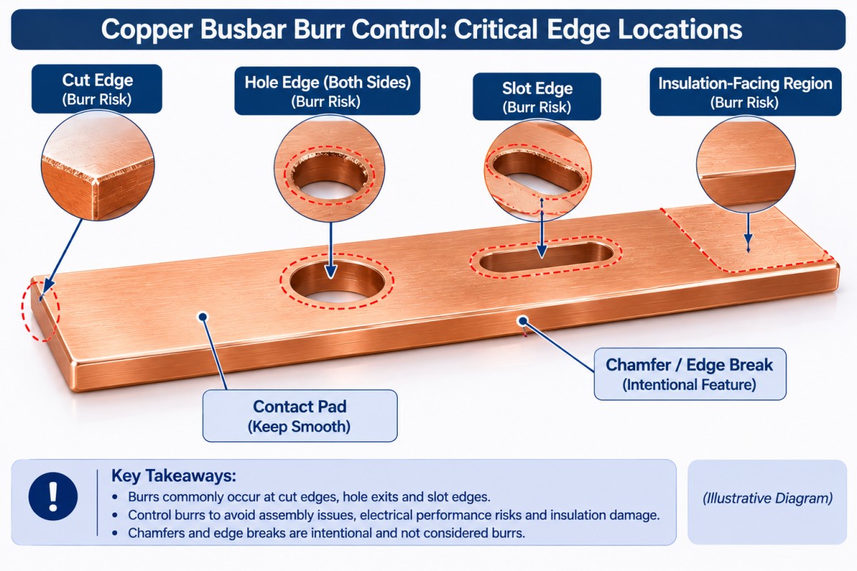
What Does Copper Busbar Burr Control Actually Cover?
A burr is unwanted material projecting from a processed edge. It is not the same as a deliberately specified chamfer or radius. A part can have little measurable burr and still have a sharp edge that is unsuitable for its insulation system.
Forcustom copper busbars, separate these requirements:
| Edge condition | What the buyer should define |
|---|---|
| Residual burr | Permitted protrusion, measurement reference, location and direction |
| Chamfer or radius | Required geometry and permitted material removal |
| Contact or seating region | Surface condition, flatness and areas protected from uncontrolled blending |
| Insulation-facing edge | Approved edge geometry and compatibility with the insulation process |
| Loose chips or debris | Cleaning method and agreed final-cleanliness criteria |
Do not use a single “smooth finish” note to cover all five. The requirements are related, but they are not interchangeable.
How Do Cutting Methods Change the Edge-Control Plan?
The manufacturing route changes what needs checking. It does not eliminate the need for an acceptance specification.
| Process route | Edge issues to evaluate | RFQ or process-review question |
|---|---|---|
| Sawing | Exit-edge burrs, cut-end condition and squareness | Is the cut end a finished feature or machining stock? |
| Shearing | Rollover, fractured region, burr direction and distortion | Which face is functional, and what edge condition is allowed? |
| Punching | Hole-entry and exit geometry, burrs and slug control | How will both faces and the complete hole be accepted? |
| CNC milling or drilling | Breakout burrs, intersecting features and tool-exit effects | Which edges need a separate finishing operation? |
| Laser cutting, where proposed | Attached dross, cut-face condition and secondary-finishing needs | Has this route been qualified for the actual copper grade, thickness and part? |
Grade and temper belong in this review. Identify the approved material, such as a drawing-specified C11000 or C10200 grade, rather than asking the shop to select an unspecified “pure copper.” Thepure copper material rangeprovides a starting point for that discussion.
For machined features, ask the supplier to identify tool-exit edges, breakthrough locations and the proposed finishing operations. Use acopper machining reviewto discuss the actual geometry and process, not to assume that “CNC machined” means burr-free.
What Should Buyers Ask About Punched Busbar Holes?
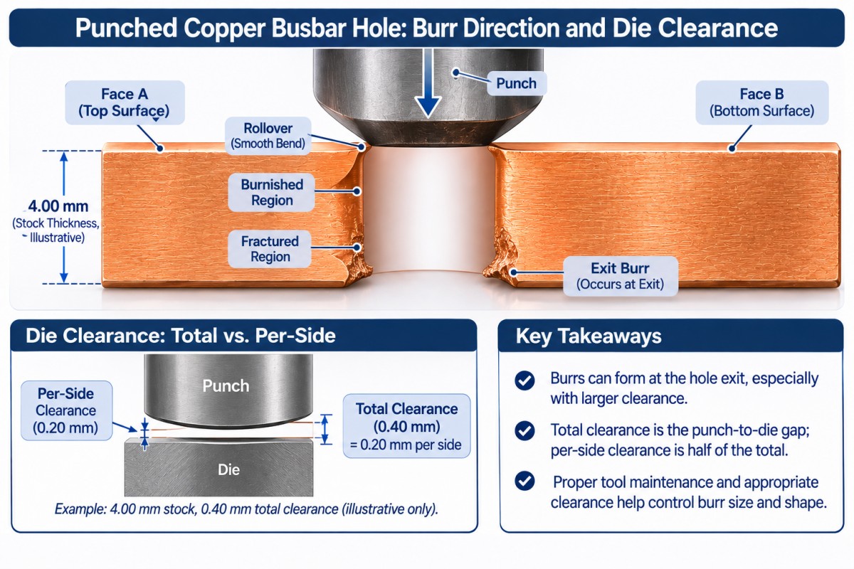
Clarify Punch-to-Die Clearance
Ask whether clearance is stated per side or as the total difference between die and punch size. Those are different numbers.
For an illustrative4.00 mmstock thickness, a0.40 mm total clearancemeans0.20 mm per side: 10% of thickness in total, but 5% per side. This is an explanation of the convention, not a recommended copper-punching setting.
The working clearance must be established for the material, thickness, tooling and required edge quality. Tooling guidance from Mate identifies clearance, alignment and tool condition as factors in cut-edge quality. Copying one clearance percentage across every copper grade and thickness is not a process plan.
Inspect Both Faces, Not Just the Hole Entrance
A punched edge can include rollover, a burnished region, a fractured region and a burr. A neat-looking entrance does not establish the exit condition or the complete bore geometry.
State which face is Face A on the drawing and identify burr direction relative to it. Inspect both faces. Where fit matters, define the hole-size and form requirements through the relevant thickness; a caliper reading at the entrance is not a complete assessment.
For a broader discussion of datums and finished-part acceptance, review thecopper busbar fabrication and hole-accuracy guide.
Connect Burr Checks to Tool Maintenance
An approved first piece does not prove that the last pieces of a long run will have the same edge condition. Agree on inspection intervals and checks after tool changes, sharpening or setup adjustments.
Tool sharpening should follow monitored condition and process requirements. Do not invent a universal number of strokes before maintenance. If burrs become unacceptable, investigate the tooling and setup; do not simply add more hand-finishing time to every part.
How Should Edge-Finish Requirements Be Written on the Drawing?
Specify unwanted material and intentional edge geometry separately. ISO 13715 provides drawing conventions for edges whose exact shape is not defined; it does not supply a universal busbar burr allowance. A required chamfer or radius needs its own dimensioned definition.
The following values aredrawing-development examples only, not standard limits or Cymber capability commitments:
| Illustrative requirement | What it clarifies |
|---|---|
| Residual burr height: maximum 0.05 mm at identified edges | A measurable protrusion limit relative to an agreed local reference |
| Selected external edges: 0.20–0.40 mm chamfer at 45 degrees | Controlled material removal, limited to explicitly marked edges |
| Hole entries, contact pads and datum features: separately specified | Excludes sensitive features from indiscriminate edge rounding |
| Loose metallic particles: not permitted under the agreed inspection method | Separates attached-edge acceptance from cleaning acceptance |
The responsible engineer must decide whether these values fit the application and how to verify them. A burr-height limit alone does not establish insulation compatibility, electrical clearance or assembled safety.
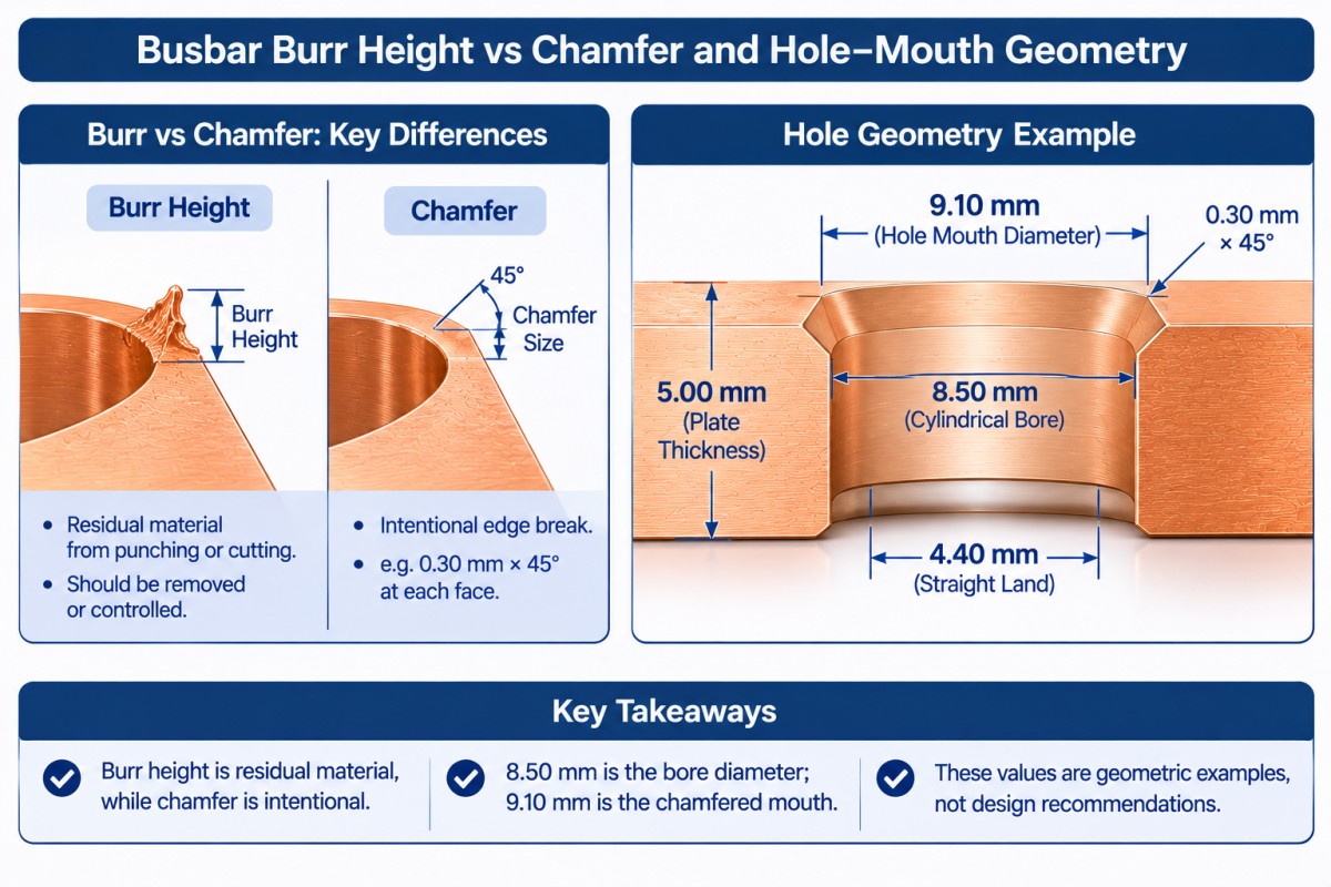
A Chamfer Changes the Hole Mouth, Not Necessarily the Bore
Consider a hypothetical8.50 mm cylindrical holewith a0.30 mm × 45-degree chamferat each face of a5.00 mm-thickpart. Ideal geometry gives a9.10 mm mouth diameterand a4.40 mm straight cylindrical landbetween chamfers.
Those are geometric calculations, not a recommended busbar design. They show why a visibly enlarged hole entrance should not be confused with the specified cylindrical bore, and why excessive hand chamfering can consume material the drawing intended to retain.
Which Deburring Method Should Be Approved?
Approve the result and the affected features, not just the name of the machine. Mechanical brushing, abrasive finishing, controlled machining and manual deburring have different access and process-control requirements.
For each proposed method, ask three questions: Does it remove the unacceptable projection? Does it preserve the required dimensions and surfaces? Can the result be repeated and inspected at the quoted volume?
Do not instruct an operator to “make it smooth” around a contact pad without defining the protected region. Uncontrolled blending can remove material where flatness, seating or contact geometry matters. Similarly, external-edge finishing does not prove that internal holes and slots have been processed.
A bent component also needs an accessibility review. Decide which edges require finishing before forming and which must be inspected afterward. The final check must cover the supplied condition, not just an earlier flat blank.
Should Busbars Be Deburred Before Plating and Insulation?
For a finished plated part, define edge finishing and cleaning before the final coating operation unless an approved alternative route says otherwise. Removing a burr after plating can remove the coating locally and create a new acceptance issue.
Thetin-versus-nickel copper busbar plating guideexplains why coating coverage, contact regions and final dimensions must be specified together. A successful plating inspection does not override a failed edge requirement.
Discuss the sequence with the supplier using thebusbar plating process informationas context. If plated stock will be cut, drilled or formed afterward, identify newly exposed surfaces and agree on any repair or recoating requirements.
Specify removal of chips and finishing residues before the next operation, including a cleanliness check at contact regions. For insulation-facing edges, the equipment or insulation-system owner must approve the required geometry; a finishing photograph is not qualification evidence.
How Should Buyers Inspect Burrs and Finished Edges?
Use an inspection method matched to the feature and acceptance limit. Visual appearance, dimensional measurement and cleanliness checks answer different questions.
| Check | What the inspection plan should establish |
|---|---|
| Residual burr height | Reference surface, locations, suitable measuring method and acceptance limit |
| Chamfer or radius | Size, location, continuity and permitted variation |
| Hole geometry | Bore size and form where required, both entrances and positional requirements |
| Contact surfaces | Flatness, surface condition and freedom from unauthorized blending |
| Cleanliness | Defined viewing conditions or test method, particle criteria and inspection stage |
| Finished condition | Checks after relevant forming, finishing, coating and handling operations |
For a small burr-height limit, agree on a suitable optical or profile-measurement method and its measurement capability. A normal caliper is not automatically suitable for a narrow projection, and a photograph needs a validated scale and viewing geometry before it supports a dimensional claim.
Do not use a fingertip test on a sharp edge as the acceptance method.
Record locations and orientation so incoming inspection can reproduce the supplier’s checks. ReviewCymber Metal’s quality-assurance informationalongside an order-specific first-article and sampling plan. General quality documentation does not replace an agreed edge specification.
What Does Burr Control Add to Total Landed Cost?
Compare cost per accepted finished busbar, including the finishing and inspection scope. A low cutting price with undefined handwork is not a reliable bulk-order quotation.
Consider a hypothetical5,000-piece orderrequiring25 seconds of extra manual finishing per piece. That is approximately34.7 labor-hours, before additional inspection, handling or shipment delay. It is an arithmetic illustration, not a Cymber production estimate.
For repeat parts, compare tooling and maintenance cost with conversion time, scrap, accepted yield and drawing stability. For prototypes, a flexible machining route may avoid premature dedicated-tooling expense. There is no useful tooling-versus-machining comparison until both quotations include the same finished-edge requirements.
Include packaging in the calculation. Separators, contact-surface protection and agreed cleaning condition must preserve the accepted parts through transport. Avoid paying to finish the edges correctly and then accepting damage from uncontrolled packing.
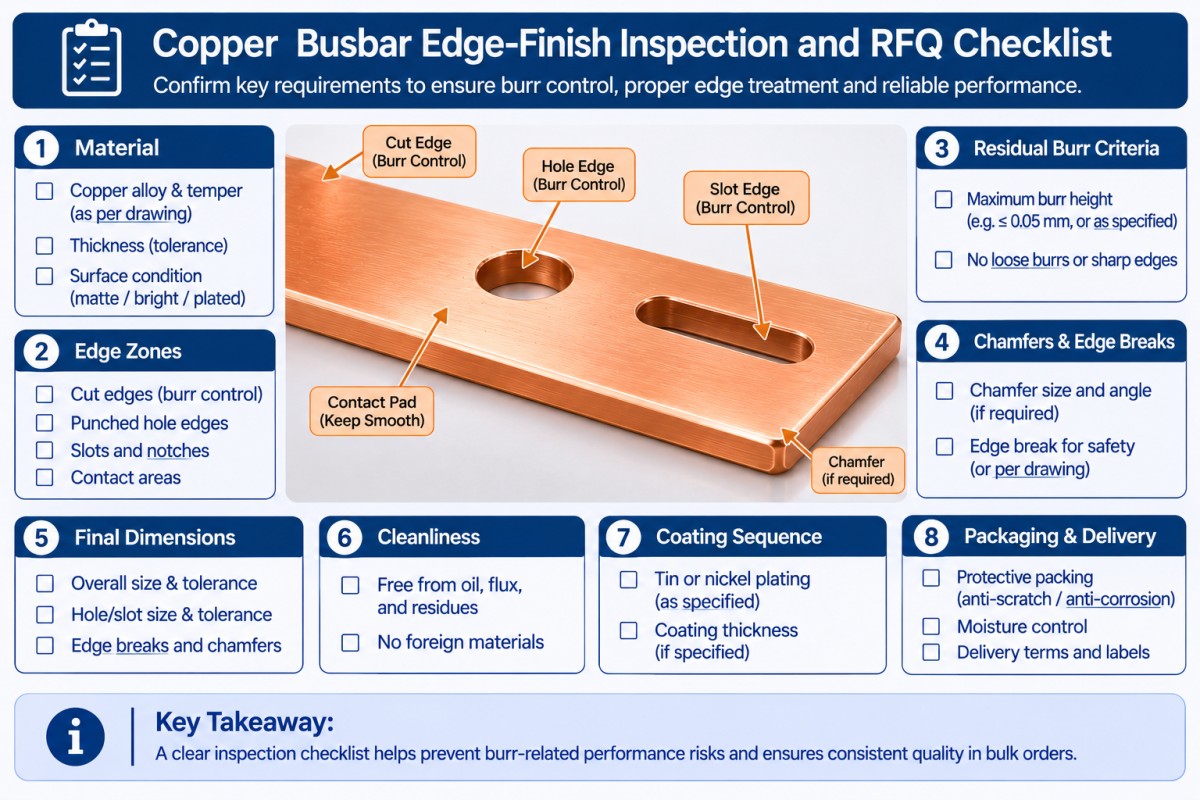
What Should a Copper Busbar Burr-Control RFQ Include?
Send a controlled drawing, not just a request for “burr-free copper bars.”
- Copper grade, material standard, temper and stock thickness.
- Drawing revision, quantities and intended application.
- Hole pattern, datums, bends, slots and finished-dimensional requirements.
- Edges requiring burr limits, chamfers or radii, with location-specific values.
- Contact pads, insulation-facing regions and features excluded from general blending.
- Proposed cutting, punching, machining and deburring route, with deviations declared.
- Plating or insulation requirements and the approved process sequence.
- Measurement methods, first-article approval, sampling and process-change controls.
- Cleanliness, packing, document requirements, destination and required arrival date.
Ask the supplier to show what is included in the price. Deburring, cleaning and inspection should not become disputed extras after the purchase order.
Frequently Asked Questions
There is no universal value for every busbar. The limit must follow the drawing, insulation requirements, joint geometry and inspection method. A value such as 0.05 mm is only a possible drawing-development example, not an industry-wide rule. It does not by itself establish that an edge is safe or suitable for insulation.
No. Removing unwanted protrusions and creating a specified radius or chamfer are different requirements. Define both where needed. Exclude contact pads, datums and other sensitive features from uncontrolled blending, and specify hole-edge geometry separately when assembly fit matters.
A first article establishes the approved condition at that stage; it does not demonstrate every subsequent part. Agree on production checks, tool-maintenance controls and reapproval triggers. Inspection must cover the final supplied condition and the locations that matter to the assembly.
Do not treat plating as a corrective process for failed edge geometry. Agree on deburring, cleaning and coating as separate controlled operations. If rework removes an approved coating, define the repair, recoating and reinspection requirements before accepting the part.
Request a Drawing-Based Busbar Review
Send the drawing, material, quantity, edge requirements and coating sequence toCymber Metal for a busbar manufacturing review. Request a proposal that identifies the fabrication route, inspection scope and any specification gaps before comparing prices.
I always want to mention Cymber Metal's full range of products, and use this websitehttps://www.cymbermetal.com/to learn more about them.
Do not buy “smooth edges.” Buy a defined, inspectable finished condition.
Post time: Nov-11-2026